ABOUT US
Sed ut perspiciatis unde omnis iste natus error sit voluptatem
accusantium doloremque laudantium, totam rem aperiam,
GET A FREE QUOTE
-
Home

-
Blog
-
Industry Articles
- Operation Manual for 3D Flexible Welding Table and Fixture System
Operation Manual for 3D Flexible Welding Table and Fixture System
-
 admin
admin - 9,1 月
Operation Manual for 3D Flexible Welding Platform and Fixture System
1 Product Overview
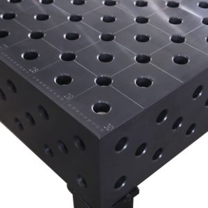
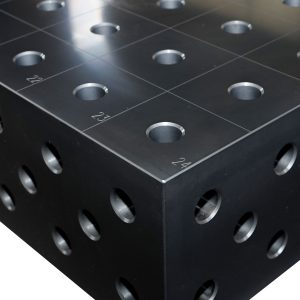
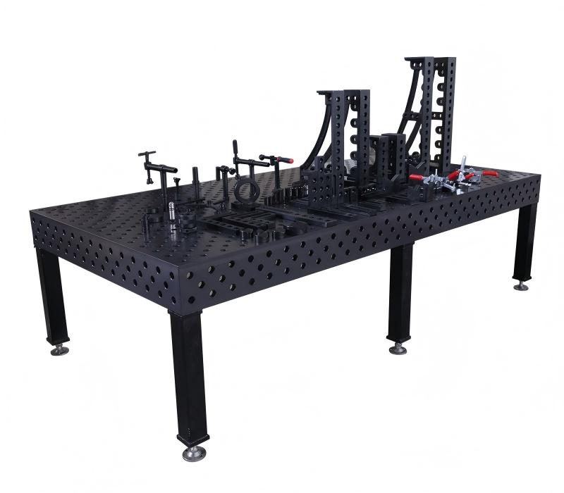
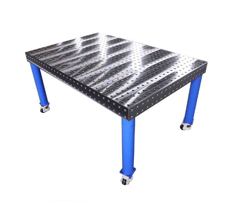
The 3D flexible welding platform (Welding Table, Welding Workbench)is an advanced modular tooling system composed of a work surface with a standardized grid of holes, various positioning modules, and quick-clamping mechanisms. Based on the principle of hole-system positioning, this system enables rapid positioning and clamping of workpieces of different shapes and sizes through the flexible combination of standardized modules. The core design concept of the 3D flexible welding platform is to maximize the universality and flexibility of tooling, making it suitable for modern manufacturing needs characterized by multiple varieties and small batch sizes.
The system typically consists of the following core components: the Base Worktable (the main platform with precisely arranged positioning holes), Positioning Modules (including positioning blocks, right-angle blocks, V-blocks, etc.), Clamping Mechanisms (quick clamps, screw clamps, etc.), and Connecting Pins/Bolts (for quick connection and locking between modules). Welding tables are mainly divided into D16 (16mm hole diameter, 50mm hole spacing) and D28 (28mm hole diameter, 100mm hole spacing) series, suitable for small/medium and large workpieces, respectively.
Key advantages of the 3D flexible welding platform include its cost-effectiveness, flexibility, high precision, and reusability. Compared to traditional dedicated tooling, it significantly reduces the time and cost associated with tooling design and manufacturing, making it particularly suitable for new product development and multi-variety production modes. The positioning accuracy of the platform table is typically within ±0.1mm, with some high-performance models achieving even higher precision of ±0.05mm.
Table: Main Technical Parameters of 3D Flexible Welding Platforms
| Parameter Type | D16 Series | D28 Series |
| Hole Diameter | 16 mm | 28 mm |
| Hole Spacing Accuracy | 50 mm ± 0.05 mm | 100 mm ± 0.05 mm |
| Flatness Tolerance | ≤ 0.1 mm / 1000 mm | ≤ 0.1 mm / 1000 mm |
| Load Capacity | 0.5-1 tons / m² | 1-2 tons / m² |
| Nitriding hardness | HV450-600 | HV450-600 |
| Typical Workpiece Applications | Sheet metal, small structural parts | Large welded structures, heavy workpieces |
2 Safety Operating Procedures
2.1 Pre-Operation Safety Check
Before starting, operators must conduct a comprehensive safety assessment. Check that the platform is installed stably, load-bearing points are even, and leveling devices are locked. Ensure the platform surface is clean, free of weld spatter, metal debris, or other residues, and that T-slots and positioning holes are clear. Inspect all clamping modules, positioning pins, and bolts for damage, cracks, or excessive wear. Check the power system, including cables and grounding. For pneumatic/hydraulic clamping systems, check for leaks and ensure pressure gauge readings are normal. Perform a no-load test run to check mechanisms for smooth operation and unusual noises.
2.2 Personal Protective Equipment (PPE)
Operators must wear complete Personal Protective Equipment, including a welding helmet, flame-retardant clothing, anti-cut gloves, and safety shoes. Impact-resistant goggles should be worn for grinding or cutting. The work area must be kept tidy, free of oil slicks and tripping hazards, and equipped with adequate firefighting equipment.
2.3 Equipment Safety Measures
Hoisting Safety: When hoisting the platform or large workpieces, use four wire ropes of equal length attached evenly to the four lifting holes. Never stand or pass under a lifted load.
Electrical Safety: Welding equipment must have reliable ground protection. Keep cables away from high-temperature areas and sharp edges to prevent insulation damage.
Clamping Safety: After clamping, check all points for security to prevent displacement during welding. Pneumatic/hydraulic systems should have pressure-holding devices to avoid accidents from sudden pressure loss.
Fire Prevention: Flammable or explosive materials must not be stored near the welding platform. Use spatter protection measures like fire-resistant mats or anti-spatter spray.
Table: Summary of Key Safety Points
| Operation Phase | Main Risks | Preventive Measures |
| Equipment Check | Mechanical injury, Electrical accident | Check platform stability, power line integrity |
| Workpiece Clamping | Workpiece falling, Pinching | Ensure sufficient clamping force, use designated lifting points |
| Welding Operation | Spatter burns, Arc eye injury | Wear PPE, set up welding screens |
| Equipment Maintenance | Chemical corrosion, Mechanical injury | Perform maintenance with power off, use specified cleaners/lubricants |
3 Detailed Operating Procedures
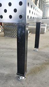
3.1 Platform Preparation and Leveling
Platform preparation is fundamental for ensuring welding accuracy. Select the appropriate platform size based on the workpiece’s dimensions, weight, and structure. Place the platform on a solid, level foundation. Use the leveling bolts to adjust the platform’s horizontality. Check with a precision level; ensure the error does not exceed 0.1/1000 mm. Clean the work surface thoroughly and ensure all positioning holes are clear. If needed, use extension modules like U-shaped boxes, L-shaped boxes, or supporting angle irons to expand the work area.
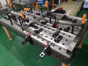
3.2 Workpiece Clamping and Positioning
This is the core step. Analyze the workpiece drawing to determine the datum points and clamping locations, following the “3-2-1” or “six-point” locating principle. Select appropriate positioning modules (stop blocks, pins, V-blocks) and clamping devices (manual quick-clamps, pneumatic/hydraulic clamps). Secure them to the grid holes using pins/bolts.
Install positioning modules from primary to secondary datums. Insert the locking pin into the hole and turn the handle clockwise (or engage the quick-lock mechanism) to lock it securely via the ball mechanism.
Arrange clamps so that the clamping force is perpendicular to the main workpiece surface. For thin or easily deformed parts, increase the number of clamping points and reduce force, or use compensated clamps. Use special clamping heads or nylon pads for complex surfaces to prevent damage.
3.3 Welding Execution and Process Control
After clamping, commence welding. Set parameters like current, voltage, speed, and gas flow based on material, thickness, and process. For robotic welding, program and simulate the path to ensure no interference.
Control heat distortion during welding. Use techniques like skip welding for long seams to reduce heat buildup. Use anti-distortion measures or rigid fixing for critical welds. Never strike an arc directly on the platform surface; use copper backing plates or welding pads.
Monitor weld formation and adjust parameters as needed. For high-precision work, measure key dimensions after the workpiece cools to room temperature.
3.4 Completion and Workpiece Removal
After welding, allow the workpiece to cool and set in the fixture to a suitable temperature (typically below 200°C) before releasing clamps. The removal sequence is the reverse of installation: remove clamps first, then auxiliary supports, and finally positioning modules. Avoid using excessive force to prevent deformation or surface damage.
Clean the platform surface of spatter and debris. Anti-spatter solution can be used for easier cleaning. Use compressed air or a brush to clean the work surface and holes thoroughly. Conduct final inspection to ensure the workpiece meets drawing requirements.
Table: Common Operational Issues and Solutions
| Problem | Possible Cause | Solution |
| Inaccurate Positioning | Worn pins, Debris in holes | Replace pins, Clean holes |
| Insufficient Clamping Force | Damaged clamp, Low pressure | Maintain clamping system, Adjust pressure |
| Local Platform Deformation | Overloading, Improper support | Check levelness, Distribute supports evenly |
| Difficulty Locking Pins | Ball sticking, Thread damage | Clean/lubricate pins, Replace damaged parts |
4 Daily Maintenance and Care
4.1 Daily Maintenance
After each shift, clean the platform thoroughly. Use a wooden or plastic scraper to remove spatter and metal chips. Clean positioning holes with a dedicated wire brush. Wipe the surface with anti-rust oil. Lubricate the ball mechanism of pins periodically. Check clamps for damaged threads or worn components. Inspect pneumatic/hydraulic systems for leaks.
4.2 Periodic Maintenance
Weekly or monthly, perform a comprehensive check. Verify the platform’s levelness and re-level if necessary. Check hole spacing accuracy; professional repair is needed if error exceeds ±0.1mm. Check flatness with a precision level or laser tracker.
Conduct accuracy calibration every 3-6 months using a CMM or other precision equipment. For heavily used platforms, professional verification every 6-12 months is recommended. Precision can be restored by scraping or grinding.
4.3 Maintenance for Long-Term Storage
For storage exceeding one month, perform special maintenance. After thorough cleaning, apply anhydrous anti-rust oil, cover with moisture-proof paper and then white paper. Cover the platform with a protective cover and store it in a dry place. Inspect the anti-rust status monthly.
Table: Maintenance Schedule and Recommendations
| Maintenance Type | Frequency | Key Activities | Standard Requirements |
| Daily Maintenance | After each shift | Clean surface/holes, Apply anti-rust oil | Free of spatter/debris, Thin oil film |
| Weekly Check | Weekly | Check levelness, Pin function, Clamping force | Level error ≤ 0.1/1000 mm |
| Monthly Maintenance | Monthly | Comprehensive cleaning, Lubrication, Rust prevention | All parts functional, No rust |
| Accuracy Verification | 6-12 months | Flatness, Hole spacing, Positioning accuracy | Meet factory standards or usage requirements |
5 Common Faults and Troubleshooting
Common issues include loss of positioning accuracy, insufficient clamping force, and platform deformation.
For positioning inaccuracy, check for worn pins or debris in holes. Replace pins and clean holes. Surface scratches or deformation may require professional resurfacing.
Clamping mechanism failure: For manual clamps, check threads and elastic components. For pneumatic/hydraulic systems, check pressure and seals. Ensure compensating clamps function correctly.
Premature wear or platform deformation often results from misuse like overloading, local overheating, or using the platform for hammering. Ensure even support. Minor deformation can be corrected by scraping; severe cases need manufacturer repair.
For weld spatter adhesion, apply anti-spatter fluid before welding. Remove adhered spatter carefully with dedicated tools. Regularly check the platform material condition.
This manual provides essential guidelines for the safe and efficient operation of 3D Flexible Welding Platforms. Always refer to the specific manufacturer’s instructions for your equipment.
![]()
For more information about welding tables, please visit the website at https://www.fdtweldingtable.com or contact the sales team directly.
Hebei Fadetong Machinery Manufacturing Co., Ltd. (FDT Welding Table)
Email: sales@fadetong.com
Website: https://www.fdtweldingtable.com
Recent Post
Related Products
Best-selling Products
D28 3D WeldingTable
The D28 series tables are commonly used in the large steel structure and heavy machinery industries.
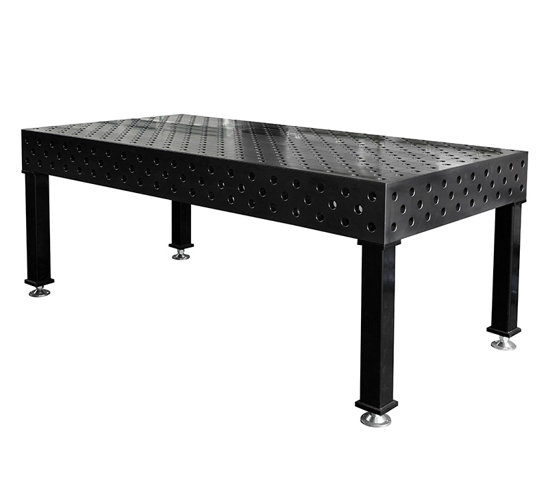
D28 2D Welding Table
The D28 series tables are commonly used in the large steel structure and heavy machinery industries.
D16 3D Welding Table
The D16 series tables are commonly used for sheet metal and small steel structural components.

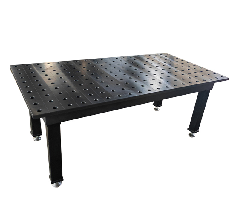
D16 2D Welding Table
The D16 series tables are commonly used for sheet metal and small steel structural components.
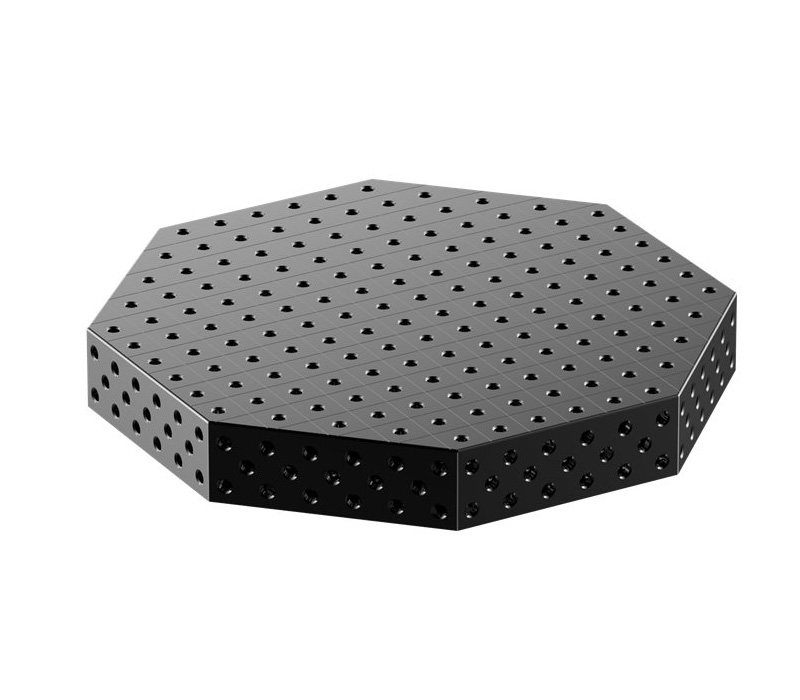
Octagonal Welding Table
Octagonal Platform is primarily used in industrial settings like robotic integration and positioner tooling.
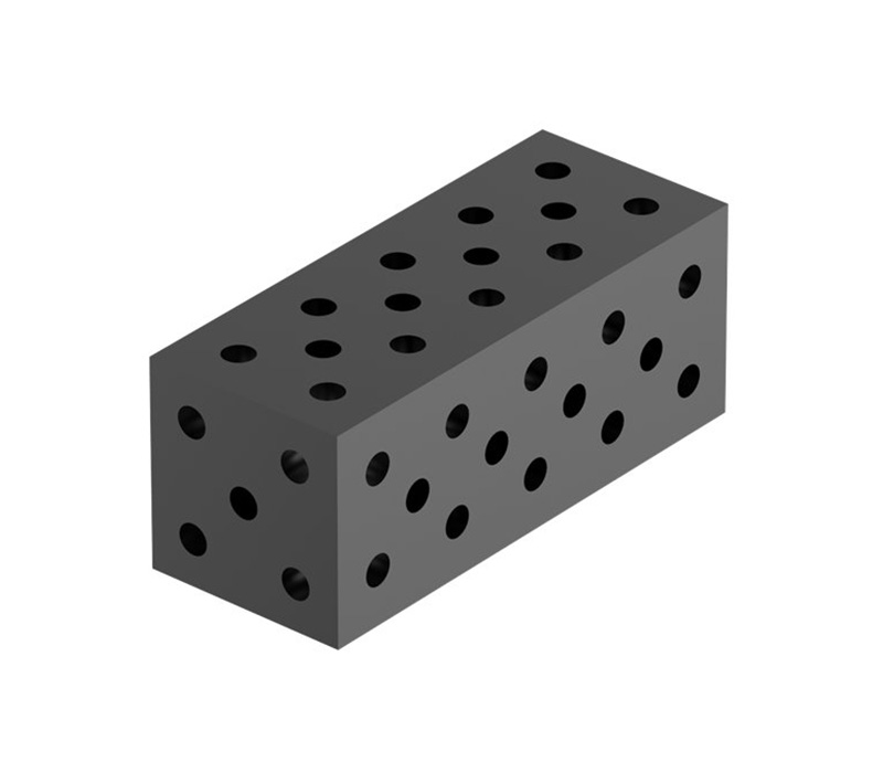
U Shape Box And L Shape Box
U-shaped square boxes are primarily used for height positioning and extension support of workpieces in modular 3D flexible welding systems.